Chapter 9
An IFR Cross Country Flight Tutorial
9.1 Introduction
In the cross country flight tutorial, you learned about VFR flight, and in the course of the flight you were introduced to most of the flight instruments in the C172p. Now we’re going to do an Instrument Flight Rules (IFR) flight. In this flight you’ll be introduced to the remaining instruments, learn a bit about IFR flight, and learn many, many TLAs (Three-Letter Acronyms).
We’ll fly the same flight, from Reid-Hillview (KRHV), runway 31R, to Livermore (KLVK), runway 25R, only this time we’ll do it in IFR conditions: a 750 foot ceiling, and 1 mile visibility. This tutorial assumes you’ve completed the cross country flight tutorial.
9.1.1 Disclaimer
This is not intended to teach you how to fly IFR. Rather, it is meant to give a flavour of what IFR flying is like, and remove the mystery of the panel instruments not covered by the cross country flight tutorial.
I’m not a pilot. Like the previous tutorial, this information has been gleaned from various non-authoritative sources. If you find an error or misunderstanding, please let me know. Mail me at bschack-flightgear -at- usa -dot- net.
9.2 Before Takeoff
We need to tell FlightGear about our flight conditions. Depending on which version of FlightGear you’re using there are different ways to set our “desired” weather. You need to check your specific version to see what you need to do. In the command-line version, you need to add the following options when you start up:
--ceiling=750:3000 --visibility-miles=1
The first option asks for a 750 foot ceiling, with a thickness of 3000 feet (ie, the cloud tops are at 3750), the second should be obvious. I strongly recommend also setting the following, admittedly hairy, option:
--prop:/environment/config/aloft/entry/visibility-m[0]=30000
The option’s not pretty,1 but the result is — when you top out at 4000 feet, you’ll be able to see for miles (30,000 metres, in fact), including a few peaks poking through the clouds (without this option, you’d have 1 mile visibility above the clouds as well as below them). It’s a small thing, and not strictly necessary, but there’s something very uplifting about rising above the clouds into a bright sunny world, with blue sky above and a carpet of white below, like Figure 9.1.
9.2.1 Flight Planning
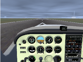
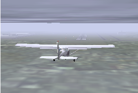
Unfortunately, when you start, you won’t see a carpet of white. You’ll see something more like Figure 9.2. Those clouds don’t look very friendly, and it’s hard to even see past the end of the runway. Maybe we should just drive there in the Cessna. We had been planning to practice ground steering anyway …
So how do you get from A to B when you can’t see? There are a variety of ways that have evolved over the years, with various advantages and disadvantages. Our flight will use all of the navigation instruments the standard Cessna C172p has, just to give a taste of what’s possible.
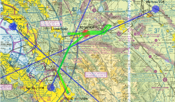
Our entire route, and the aids we’ll be using, are shown in Figure 9.3. Our route is in green, the navigational aids blue and red. The route looks a bit crazy — in fact, you might wonder if we’re more lost using our fancy equipment than just flying by the seat of our pants — but there is a method to the madness. Rather than overwhelming you with details by explaining it all now, I’ll explain it bit by bit as we go along.
9.2.2 VHF Omnidirectional Range
The first bit will involve VOR 2 (VHF (Very High Frequency) Omnidirectional Range) navigation, and will get us to a point about 5 nm (nautical miles) south of Livermore.
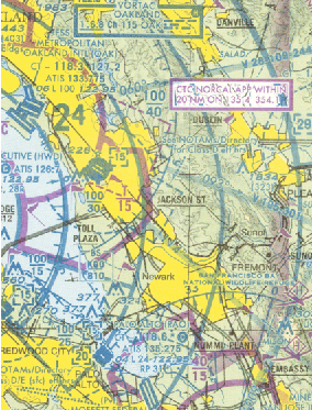
VOR stations are indicated on the sectional by a big bluish-green circle with compass markings around the outside. I’ve helped you by marking their centers with a big blue dot as well. Reid-Hillview is very close to one, San Jose, which you can see in Figure 9.3. Near the centre of the circle, in a bluish-green rectangle, is the station information. According to the station information, it’s a VOR-DME station (I’ll explain DME later), its name is San Jose, its frequency is 114.1 MHz (or Channel 88, which is an alternative way to say the same thing), and its identifier, or “ident”, is SJC (which in Morse code is ....--- -.-.).
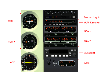
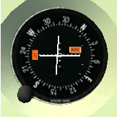
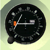
To tune into a VOR station, we use one of the NAV receivers, which are paired with the COMM receivers (see Figure 9.4). And we navigate using the corresponding VOR gauge. We’ll choose the NAV1 receiver (and VOR1 gauge) in this case (NAV2 would have worked just as well). Before setting the frequency, check out the VOR1 gauge. It should look like VOR1 on the left in Figure 9.5. The important thing is the red “NAV” flag. That means there’s no VOR signal, so we can’t trust the gauge.
The NAV receiver has an active frequency, a standby frequency, and a tuning knob, just like the COMM receiver.3 Tune it to 114.1, and press the swap buttonNAV1 ⇒ 114.1 4. If you look at VOR1, you should notice that the red “NAV” flag has disappeared, to be replaced with a “TO” flag, as shown on the right of Figure 9.5. That means we’re receiving a signal. But is it the correct one? What if we accidentally set the wrong frequency?
To confirm that we’re tuned into the correct VOR, we listen for its ident. If you can’t hear the ident, or if it doesn’t match the chart, don’t trust the needle. So far, you probably haven’t heard a thing. That seems strange. After all, the red “NAV” flag turned off. We must be in range of some station, right? Why can’t we hear anything?
When in doubt, look for the simplest solution. In this case, check the volume. There’s a little knob on the NAV receivers, with “PULL IDENT” written beside it (see Figure 9.6). That’s our ident volume control. It’s pointing down and to the left in the picture, which means the volume is off. Click on the right side of the ident knob to increase the volume. Now you should hear the ident: . . .. - - - - . - . . Phew.
Back to VOR1. There’s a knob on the lower left, called the OBS (Omni Bearing Selector). As the name vaguely suggests, it is used to select a bearing. If you turn it, you should see the vertical needle, called the CDI (Course Deviation Indicator) move.5 Try to center the needle. It should center when the little arrow at the top points to somewhere around 277. That number, and the TO flag means: “Flying at a heading of 277∘ will lead you directly to the station”.
That’s great, except, according to our route, we don’t want to go to the station. We actually want to intercept the light blue line labelled “009∘” (the “9 degree radial”) coming from the station. How do we do that? Simple. Set the OBS to 9VOR1 OBS ⇒ 009. When we fly across the radial, the needle will center, and the flag will say FROM. This tells us: “flying at a heading of 9∘ will lead you directly away from the station”, which is what we want. At that point we’ll turn right to a heading of 9∘.
One final thing — set the heading bug on the directional gyro to our current heading (about 310∘)Heading bug ⇒ 310.
9.2.3 Takeoff
Now we’re ready to take off. It took a long time to get ready, but in fact there’s really more that we should have done. For example, there are all the things mentioned in the previous cross country flight tutorial. And there are other IFR preparations that we should have made. But again, in the interests of not overwhelming your brains, I’m only feeding you a bare minimum of information, and feeding it in trickles. This brings us to the most important control you have — the ‘p’ key. Use this often, especially when a new concept is introduced.
Okay. Now take off, keeping a heading of 310∘ for nowTake off; climb on runway heading. Establish a steady rate of climb. We plan to climb to 4000 feet. There’s just one problem though — those ugly-looking clouds are standing in our way.
9.3 In the Air
If this is your first attempt at IFR flight, you will find it impossible to fly once you enter the clouds. When you enter the clouds, you will be momentarily disconcerted by the lack of visual cues. “No matter,” you then think. “I’ll just keep things steady.” In a few moments, though, you’ll probably notice dials and needles spinning crazily, and without knowing it, you’ll be flying upside down, or diving towards the ground, or stalling, or all three.
It takes practice to get used to flying without external visual clues, although it’s a skill that you definitely must master if you want to fly IFR. For now though, we’ll use “George”, the autopilot, to make this part of flying easier.
9.3.1 George I
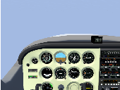
Once you’ve established a steady rate of climb and heading, engage the autopilot by pressing the AP button. You should see “ROL” displayed on the left to show that it’s in “roll mode” — it is keeping the wings level. In the middle it will display “VS”, to show it is in “vertical speed” mode — it is maintaining a constant vertical speed. On the right it will momentarily display that vertical speed (in feet per minute). Initially, the value is your vertical speed at the moment the autopilot is turned on. In the case of Figure 9.7, the autopilot has set the vertical speed to 300 feet per minute.
When you engage the autopilot, CHECK THIS CAREFULLY. Sometimes the autopilot gets a very funny idea about what your current rate of climb is, like 1800 feet per minute. Our little Cessna cannot sustain this, and if the autopilot tries to maintain this (and it will), you will stall before you can say “Icarus”. This is a bug, to be sure, and a bit annoying, but it is also a useful cautionary lesson — don’t put blind faith in your equipment. Things fail. You have to monitor and cross-check your equipment, and be prepared to deal with problems.
We want a vertical speed of around 500 to 700 feet per minute. Hit the up and down (UP and DN) buttons to adjust the vertical speed to a nice value. Take into account the airspeed as well. We want a sustainable rate of climb.
Finally, once you’re climbing nicely, hit the heading (HDG) buttonEngage autopilot; set vertical speed; engage heading mode. On the display, “ROL” will change to “HDG”, and the autopilot will turn the airplane to track the heading bug. Since you set the heading bug to the runway heading, and you took off straight ahead (didn’t you?), it shouldn’t turn much.
9.3.2 MISON Impossible
It’s around 8 nm to the 009 radial intercept, so we’ve got a bit of time. Since there’s no scenery to admire (eg, see Figure 9.8 ), we might as well prepare for the next phase of the flight.
If you look along our route, just after we intercept the 009 radial and turn north, we pass by a point labelled MISON (see Figure 9.9 for a closeup of that section of the chart without my fat blue and green lines drawn on top. MISON is in the lower right). Just above and to the left of MISON are two crossed arrows. MISON is an intersection. We’re actually going to pass east of MISON, but the radial passing roughly from northwest to southeast through MISON (and our route) is of interest to us. We’re going to use it to monitor our progress.
Noting our passage of that radial isn’t strictly necessary — we can just keep flying along the 009 radial from San Jose until we need to turn. But it’s useful for two reasons: First, it’s nice to know exactly where we are. Second, it confirms we are where we think we are. If we fly and fly and never cross the radial, alarm bells should start going off.
Looking at the sectional, we see that the radial is the 114 radial from the Oakland VORTAC (VOR TACAN, where TACAN stands for Tactical Air Navigation). Oakland’s frequency is 116.8, and its ident is OAK (- - - . - - . - ). NAV2 should already be tuned to Oakland, but if it isn’t, do it now.NAV2 ⇒ 116.8 Turn on NAV2’s volume and make sure you’re getting the correct ident.
We need to adjust the OBS, to tell VOR2 which radial we’re interested in. Set the OBS to 114VOR2 OBS ⇒ 114.6 See if you can guess whether the flag should read TO or FROM when we cross the 114 radial. And see if you can guess whether the needle will move from left to right or right to left as we cross the radial.
A final note: For our purposes, there’s nothing magical about the 114 radial — we could have used 113, or 115, or 100, or 090. The reason I chose 114 is because there was a line on the map already drawn along the 114 radial, which saved me the trouble of drawing a line myself.
9.3.3 George II
As we continue towards the 009 radial intercept, let’s look a bit more closely at the autopilot. First of all, if you aren’t in the habit of trimming the airplane, you’ll probably notice a flashing “PT” with an arrow on the autopilot. The autopilot is telling you to adjust the pitch trim. I tend to ignore it because, flying with a mouse, trimming is more trouble than it’s worth. Those of you lucky people with yokes and joysticks and who find flashing lights annoying might want to trim to get rid of it.
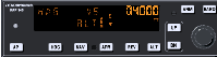
Also, on the right there’s a big knob, the altitude select knob, which we can use to dial in a target altitude. We’re going to use it. Turn it until you see our desired cruising altitude, 4000 feet, displayed on the right. When you started turning it, “ALT ARM” should have appeared in the autopilot display (as in Figure 9.10). This indicates that you’ve selected a target altitudeSet autopilot altitude to 4000. The autopilot will maintain the current rate of climb until reaching that altitude, at which point it will level off and change from vertical speed (VS) mode to altitude hold (ALT) mode. In altitude hold mode it maintains an altitude (in this case our target altitude of 4000 feet). 7
Don’t forget that the autopilot won’t adjust the throttle, so when it levels out, the airplane (and engine) will speed up. You’ll need to adjust the throttle to get a proper cruise.
9.3.4 Staying the Course
At some point you’ll intercept the 009 radial (the VOR1 needle will centre). Turn to a heading of 009Turn to 009∘ upon VOR1 intercept. You can do this using the heading bug on the directional gyro if you’re using the autopilot.
Unless you’re good or lucky, the needle probably won’t be centered. We need to adjust our course. The CDI needle (the vertical needle on the VOR) tells us where to go. If it’s to the left, that means the radial is to the left, so we need to go left. Ditto for right.
It’s quite easy in theory, although in practice you may find that it’s hard to keep the needle centered, and that you are slaloming down the radial. The key is to realize this: the position of the needle tells us where we are, the motion of the needle tells us what to do.
I’ll explain. If the needle is to our left, then, yes, the radial is definitely to our left. 8 But if the needle is moving towards us, that means we’re going to cross the radial, sooner or later, so our situation is improving, and we probably just need to wait for the needle to center. On the other hand, if the needle is moving away, we need to turn towards it to stop, and reverse, its motion.
Note that the amount we need to turn is difficult to guess correctly at first, so experiment. Try 10∘. If the needle moves too fast, cut it down to 5∘ (ie, turn back 5∘). If, on the other hand, the needle moves too slowly, double it to 20∘ (ie, add another 10∘), and see what happens.
9.3.5 Yet More Cross-Checks
Cross-checking your position is always a good thing. The intersection with the Oakland 114 radial is one wayCross OAK 114 radial. Ahead of that lies the SUNOL intersection. If you look closely, 5 separate radials join at the point, so we have an embarrassment of choices with regards to the intersecting radial. Because it will come in useful later, we’re going to use the one coming in from the upper right. Another check of the sectional reveals that this is the 229 radial of the Manteca VORTAC, 116.0 MHz, ident ECA (. - . - .. - ).
You should know the drill by now: Tune NAV2 to 116.0, set the OBS to 229, and check the
ident to confirm the stationNAV2
⇒ 116.0
VOR2 OBS ⇒
229.
Meanwhile, let’s introduce another piece of gear on the panel that will cross-check the SUNOL passage. Some VOR stations have a distance capability, called DME 9 (Distance Measuring Equipment). For example, San Jose does (remember it’s a VOR-DME station), as do Oakland and Manteca (VORTACs have DME capabilities).
Using DME, you can find out how far you are, in straight-line distance, from the VOR station. In our scenario, the DME isn’t necessary, but we’ll use it anyway, just to see how it works, and to reconfirm our position.
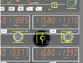
The DME is the instrument below the autopilot (refer to Figure 9.4 ). Make sure it’s turned on. The selector to the left of the on/off switch is probably set to N1, where “N1” means “listen to NAV1”. Since NAV1 is tuned to San Jose, it’s telling us the distance to the San Jose VOR-DME. Switch the DME to N2DME ⇒ N2. It now shows us the distance to the Manteca VOR.
The DME shows you 3 things: the distance in nautical miles to the station, your speed towards or away from the station, and estimated time to the station at the current speed. Note that the distance is the direct distance from your plane to the station (called the “slant distance”), not the ground distance. Note as well that the speed is relative to the station, so unless you’re flying directly to or from the station, it will probably be lower than your true groundspeed. For example, the speed from San Jose, which is directly behind us, should be greater than the speed towards Manteca, which is off to the right.
If we look up information about the SUNOL intersection,10 it tells us that it is 33.35 nm (as measured by a DME receiver) from ECA on the 229.00 radial (that’s what “ECAr229.00/33.35” means).
Now we have two ways to confirm the SUNOL intersection: The VOR2 needle will center, and the DME will read 33.4 or so. Note that the DME doesn’t provide us with a very precise fix here because Manteca is at such an oblique angle. But it does give us a good warning of SUNOL’s impending arrival. Moreover, if it has an unexpected value (like 30), it should raise a few alarm bells.
You may be wondering what “HLD” means (the setting between N1 and N2 on the DME). It stands for “hold”, and means “retain the current frequency, regardless of whether NAV1 or NAV2 are retuned”. For example, if we switch from N2 to HLD, the DME will continue to display (and update) information to Manteca. Even if we retune NAV2, the DME will remain tuned to Manteca. This is handy, because it basically represents a third independent receiver, and in IFR flight two receivers just never seem like enough.
9.4 Getting Down
We’re getting close to SUNOL, flying along the 009 radial from San Jose, monitoring our position with the DME. At SUNOL we’ll be less than 5 nm from Livermore, somewhere down there in the clouds. Perhaps if we just descended to 700 feet or so (Livermore is at 400, the ceiling is at 750) and headed more or less directly north after SUNOL, we’d get there? A recipe for disaster my friend, and you know it.
9.4.1 Instrument Approach Procedures
As you recall from the previous tutorial, when flying VFR, you don’t just point your airplane to the nearest runway to land. You need to fly a pattern. This helps you line up, and helps prevent planes from crashing into one another, which is a Good Thing.
Similarly with IFR landings. There’s a procedure to follow. In fact, there are procedures to follow. Because of the complexity of landing in IFR conditions, there’s no single procedure for all airports. You need to check for your particular airport. In fact, you usually need to check for your particular airport, runway, and navigation equipment.
Our airport is Livermore (KLVK). Let’s check the information for that airport. Go to http://www.airnav.com/airport/KLVK to see what they’ve got. Down near the bottom, we have IAPs (Instrument Approach Procedures). There are two listed for runway 25R. One is an ILS (Instrument Landing System) approach, the other a GPS (Global Positioning System) approach. Our plane has no GPS, but it does have ILS capabilities (I’ll explain ILS later), so we’ll choose that.
Although Livermore only has two different instrument approach procedures, big airports have many many more. If you look at nearby San Francisco, you’ll see they have a slew of procedures. There are ILS procedures, GPS procedures, LDA procedures, VOR procedures, … I wouldn’t be surprised if they had a procedure for someone with a sextant and an hourglass in there. To learn IFR flight, you’ll need to master all of them.
Back to Livermore. If you download the procedure, you’ll see something like Figure 9.11 (except for the colour). It’s pretty overwhelming at first — it compresses a lot of information in a small space. We’ll ignore as much as we can, restricting ourselves to the three parts that have been coloured in. And we’ll do those parts on a “need to know” basis — we’ll only look at them when we really have to.
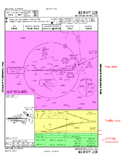
Where to start? At the beginning of course. An IAP will have one or more Initial Approach Fixes (IAFs). These are your entry points to the approach procedure and can be found in the “plan view”, which I’ve coloured purple in Figure 9.11. Our IAP lists two, one in the middle and one on the right (see Figure 9.12 for a close-up).
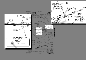
An IAF is a fix, and a fix is an identifiable point in space. In fact, we’ve already encountered another kind of fix, namely a VOR intersection. Fixes are also usually named (eg, MISON, SUNOL). The IAF on the right is named TRACY, and consists of a radial, a distance, and an altitude. Specifically, it’s 15 DME (15 nm as measured by a DME receiver) along the 229 radial from the ECA (ie, Manteca) VOR.
9.4.2 Nondirectional Beacons
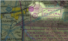
However, we’re not going to use TRACY as our IAF. We’re going to use the IAF in the middle, which is a marker (LOM stands for “Locator Outer Marker”). We’ll worry about what an outer marker is later. For now let’s concentrate on the locator part. The locator in an LOM is an NDB11 (nondirectional beacon). It’s a bit like a VOR, in that it can be used to determine your heading and navigate from place to place. Like a VOR, it has a name (REIGA, in this case), a frequency (374 kHz), and an ident (LV, or. - . .. . . - in Morse). NDBs also appear on sectionals, as fuzzy red circles with a small circle in the middle, with their identification information placed in a red box nearby. (see Figure 9.13 for a closeup. Don’t confuse the NDB, which is fuzzy, with the solid red circle on the left, nor the circle below with the “R” inside).
An NDB station basically broadcasts a signal that says “I’m over here”, and the receiver on the plane can receive that signal and tell you, the pilot, “the station is over there”. You just need to tune the receiver and monitor the correct instruments. The receiver, labelled ADF (Automatic Direction Finder) Receiver, and the corresponding instrument, also labelled ADF, are shown in Figure 9.4 .
To tune into REIGA, turn the tuning knob on the receiver until 374 is displayed as the standby (STDBY) frequencyADF ⇒ 374. As usual, use the middle mouse button for big changes (100 kHz in this case), and the left mouse button for small changes (1 kHz). Then hit the swap button (labelled “FRQ”). The 374 is now displayed as the selected (SEL) frequency. The needle on the ADF should swing around, eventually pointing ahead to the right, to REIGA. But it won’t. Why? Because the receiver is in antenna mode (as show by the “ANT” in the upper-left portion of the display).12 Hit the ADF button so that “ADF” shows. Now the needle should swing to point to REIGA.
Like VORs, to be sure we’re really tuned into the right station, we need to hear the ident as well. Like the NAV receivers, the ADF receiver has a dedicated volume control, this one labelled “VOL”. The volume also functions as an on/off switch, so if you turn it all the way counter-clockwise, it will shut the receiver off. Unfortunately, at the time of writing, the ident function doesn’t work.
Notice there’s no OBS to set for an ADF — the needle just points to the station, which is nice. This leads us to our first rule for ADFs:
- ADF Rule 1:
- The needle points to the station.
Pretty simple. In fact, you may not think it merits a “rule”, but it’s important to emphasize the difference between ADFs and VORs. A VOR, remember, tracks a single radial, which you specify by turning the OBS. An ADF has a knob, and a identical-looking compass card, so it’s tempting to believe it acts the same way. It doesn’t. Turn the ADF heading knob (labelled “HD”) and see what happens. The compass card moves, but the arrow doesn’t. It just points to the station.
In our current situation, where we just want to fly to REIGA, that’s all we need to know to use the ADF. If the needle points “over there”, then we’ll fly “over there”, and eventually we’ll pass over REIGA. However, for the sake of practice, and because it will be necessary later, I’m going to give the second rule for ADFs, which explains what the compass card is there for:
- ADF Rule 2:
- If the compass card reflects our current heading, then the needle gives the bearing to the station.
In other words, the compass card gives “over there” a number.
Now we’re ready to head to REIGA. Rotate the ADF heading knob until our current heading is at the top (basically, the ADF should match the directional gyro). When we pass the SUNOL intersection, look at the ADF needle, and set the DG bug to that heading (I assume you’re using the autopilot. If not, just turn to that heading). At the end of the turn, the ADF needle should point straight ahead.Cross SUNOL; turn to REIGA And if it doesn’t, adjust your heading so that it does.13
By the way, the closer you get to REIGA, the more sensitive the needle becomes to changes in your heading. Don’t go crazy trying to keep the needle centered as you get close. Maintain a steady heading, and get ready for the …
9.4.3 Procedure Turn
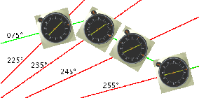
So, once we hit REIGA, do we just turn left and head down to the runway? Ah, if only life were so simple. No, we turn right, away from the airport, and do a procedure turn. We know there’s a procedure turn because of the barbed arrow in the plan view (see Figure 9.14). As you can see if you follow the arrow, we need to fly away, on a heading of 075∘, then turn left 45∘ to a heading of 030∘. We do a U-turn (to the right, away from the airport — that’s one of the rules about procedure turns) to come back at 210∘, then a 45∘ right turn to 255∘, heading straight towards the runway. All of this turning gives us time to set ourselves correctly on course, at the right altitude, to land on 25R.
Hmmm. I mentioned “right altitude”, but how do we know that is? That’s down below, in the profile view (the yellow part of Figure 9.11 ). You can see that at the top is the LOM, our IAF. Now follow the arrows. After the IAF, we head out at 075∘. During the procedure turn we can descend to 3300 feet, but no lower (that’s what the line under the 3300 means). After we finish our procedure turn and are heading back at 255∘, we can descend to 2800 feet, but no lower, until we intercept the glide slope.
One thing the instrument approach procedure does not tell you is the length of the procedure turn. The only constraint is that you must not fly more than 10 nm away from the NDB. You’ll notice there’s a 10 nm circle drawn around it in the plan view, and a note in the profile view saying “Remain within 10 NM”. They’re not kidding. So, since we fly at around 110 knots, two minutes on each leg is reasonable — two minutes at 075∘, and two minutes at 030∘. On the way back we don’t care about times — we just want to intercept 255∘.
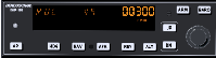
So, after we pass REIGA, turn right to 075∘. Our ADF receiver has a built-in timer, so we’ll use that to time our two-minute leg. Hit the “FLT/ET” (flight time/elapsed time) button. The “FRQ” in the middle of the display will disappear, “FLT” will appear on the right, and the standby frequency will be replaced by a time. This is the total flight time, and cannot be changed, except by cycling the power. Hit “FLT/ET” again. Now you’ll see “ET” displayed, and a time, probably the same as the flight time. To reset the elapsed time, hit the next switch, labelled “SET/RST”. The timer should reset to 0, then start counting up (see Figure 9.15 ).14 In elapsed time mode, each time you hit “SET/RST”, the time resets to 0. If you want to see the standby frequency again, hit “FRQ” once. The timers will continue to run.
9.4.4 Chasing the Needle
When we approached REIGA, we weren’t particularly concerned about our course — we just aimed for REIGA. Now, however, our course is important. We want to be flying directly away from REIGA on a course of 075∘Cross REIGA; fly at 075∘ away from REIGA for two minutes.
Now, in an ideal world, after we turned to 075∘, the ADF needle would be pointed directly behind you (ie, we’d be on course). Probably it isn’t, so we need to adjust our course. The key to adjusting our course is ADF Rule 2. If we’ve set the compass card correctly, then the needle shows us the current NDB bearing. If we turn and fly until we intercept the 255 bearing, then turn to 075∘, we’ll be right on course.
Figure 9.16 shows what I mean. In the figure, the plane, flying along the green line, is initially off course.15 The heading is correct, 075∘, but the station is at 225∘, not 255∘. To correct this, we turn right (remembering to adjust the ADF compass card to match our new heading). As we fly on this new heading, we get closer to the correct position, crossing the 235 and 245 bearings (shown in red). Finally, when we the ADF needle points to 255∘, we turn left to 075∘, and readjust the ADF compass card.16 We are now on course.
Of course, even when you get back on track, that won’t be the end of the story. Your airplane drifts; your mind drifts; your compass drifts; the wind pushes you around. What you find is that you will be constantly making little corrections. That’s okay, as long as we’re close. And anyway, before long (2 minutes actually), we’ll turn left 45∘ to 030∘ as part of our procedure turn, at which point we’ll just ignore the NDB anyway. Sigh. All that effort for just 2 minutes. Hardly seems worth it.
9.4.5 FOOTO Time
While you’re flying outbound, take an occasional look at VOR2, tuned to Manteca, and the DME. Assuming the OBS is still at 229, and the DME still tuned to N2, at some point the needle should center, meaning you’ve crossed the 229 radial, and, if you’re on course, at the same time the DME should read 20.8. How do I know that? If you look at the approach plate (Figure 9.11), you’ll notice an intersection, named FOOTO. FOOTO is on the approach, and is defined to be 20.8 DME from ECA. Although this intersection is not strictly necessary for us, it comes for free, and provides good confirmation of our position both outbound and, later, inbound.
Depending on how fast you’re flying, you’ll probably pass FOOTO close to the time your two minutes at 075∘ are up. At the end of two minutes, turn left 45∘ to 030∘. Reset the timer, and fly for another two minutes on this heading.
9.4.6 George III
This leg is relatively uneventful, so we’ll take advantage of the lull in the action to descend to 3300Turn left to 030∘; fly for two minutes while descending to 3300. Assuming you’re using the autopilot, you will need to do a few things:
- If you’re in altitude hold (ALT) mode, you need to get back into vertical speed (VS) mode. Press the ALT button — the “ALT” in the middle of the display should change to “VS”, and your current vertical speed (probably 0) should be displayed momentarily on the right.
- Click the DN button until you get a vertical speed of -500 feet per minute.
- If you want to set the target altitude, like before, rotate the big knob on the right until “3300” shows up on the right side of the display. “ALT ARM” should appear on the bottom.
Note that if you’re using the autopilot to descend, it will just push the nose down, like a bad pilot, so the airplane will speed up. We want to go down, but we don’t want to speed up, so we need to reduce engine RPMs to keep the speed at 110 knots. Later, when you level off at 3300 feet, you’ll have to increase power again.
If you’re flying manually, then you just need to adjust the engine to get the descent rate you want — the plane should stay magically at 110 knots if it’s already trimmed for 110.
9.4.7 ILS Landings
While descending, we also need to start considering how we’re going to intercept 255∘ on the way back and follow it down to the runway. You might think we’re going to use the NDB like we did on the outbound leg, but at this point, the NDB is not good enough. This is an ILS landing, a so-called “precision” landing, and an NDB is just not precise enough. It can get us close to the runway, but not close enough.
So, we’re going to switch over to our ILS system. It is much more accurate horizontally. As well, it offers vertical guidance, something which the NDB does not give at all. And hey, it also gives you something else to learn in our few remaining minutes so that you don’t get bored.
As with NDB and VOR navigation, the ILS system17 has a transmitter (or transmitters — a localizer and a glide slope) on the ground, and a receiver and a gauge in the aircraft. The receiver, it turns out, is just a NAV receiver, of which we have two. The gauge is like a VOR indicator, but it has an added glide slope indicator, which is a horizontal (you hope) needle. Like a VOR, the vertical needle shows whether you’re left or right. The horizontal needle shows whether you’re high or low. Our ILS gauge is our old friend VOR1.
As you might have guessed, the localizer has a frequency and ident associated with it (there’s no need to tune the glide slope separately. If you tune the localizer, you’ve tuned the glide slope). This is shown on the approach plate in two places: at the top left corner, and in the plan view by the runway (see Figure 9.17). As we can see, the frequency is 110.5 MHz, and the ident is I-LVK (. .. - . .. . . - - . - ).
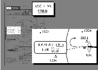
If you look at VOR1 now, it should be showing a red “GS” flag (this can be seen in Figure 9.5). This indicates that there is no glideslope signal. Now tune NAV1 to 110.5NAV1 ⇒ 110.5. The red “GS” flag should disappear. Check for the ident. Sounds lovely, doesn’t it? That localizer is going to save your bacon and get you out of this interminable soup. When you tuned into the localizer, you’ll also have noticed the ILS needles move. And the OBS? Well, it’s useless. Try moving it. No matter how you turn it, the needles don’t move in response. That’s by design. A localizer is basically a VOR with one radial, the approach heading. We don’t care about any others, so we don’t need an OBS to declare interest in any others. However, it does serve as a useful reminder, so move the OBS to 255, our desired headingVOR1 OBS ⇒ 255.
9.4.8 Intercepting the Localizer
We’re now ready to intercept the ILS localizer. When the two minutes on the 030∘ leg have passed, make your U-turn to the right to 210∘Turn right 180∘ to 210∘. Soon after you complete your turn, the vertical (localizer) needle on the ILS will begin to move. And it will move fast, much faster than the ADF and VOR needles didIntercept localizer. A localizer is 4 times as sensitive as a VOR, relatively small movements of the aircraft make big changes in the needles. You’ll probably overshoot, but don’t worry, because we have around 5 or 10 minutes to get things straightened out.
Just remember: don’t chase the needles. That mantra is now more important than ever. Those needles are sensitive — if you just turn left when the localizer needle is to the left and right when it’s to the right, you’ll be flying like a drunken sailor. If you’re lucky, the runway will be passing underneath you as you swing across the track for the umpteenth time. Luck, though, is something we should not be relying on. Determine on how the needles are moving before making your move.
Now that you’re heading back inbound at 255∘, slow to 75 knots, drop a notch of flaps, and descend to 2800 feet (but no lower)Slow to 75 knots; drop a notch of flaps; descend to 2800. And check for the inbound passage of FOOTO to confirm your position. And pat your head and rub your stomach.
9.4.9 Intercepting the Glide Slope
As we fly drunkenly towards the runway, cursing localizers and needles and resolving never, ever to fly in such crappy conditions ever again, don’t forget to look at the horizontal needle, the glide-slope needle. At the start it was high above us, because we were actually under the glide slope. But as we levelled out at 2800, the glide slope started coming “down” to us. Eventually, you should see the needle start to move down. When the needle is horizontal, that means you’re on the glide slope. You won’t be for long, though, unless you start descending.
What’s a good rate? It depends on our groundspeed. In our case, we’re going at 75 knots (there’s almost no wind, so our airspeed and groundspeed are the same), and it turns out that we need to descend at around 400 feet per minute. With the autopilot, that’s pretty easy — just dial in -400, and you’re set (but remember to reduce power to keep our speed at 75 knots, or you’ll hit the runway going pretty fast, and be prepared to adjust things if you drift above or below the glide slope).Intercept glideslope; cross outer marker; drop second notch of flaps
Without the autopilot, it’s also pretty easy — just reduce power. How much? In this case, with our plane, to around 1700 RPM. Again, it depends on many things — plane, elevation, winds, weight, …, so you’ll have to adjust things if you see the glide-slope needle start to move up or down. Like the localizer needle though, … (are you ready?) DON’T CHASE IT. Watch how it’s moving, then make your adjustment.
Since we’re on final approach, you might want to drop a second notch of flaps. This will affect your trim, and you’ll have to adjust power a bit as well.
Soon after we intercept the glide slope, we should pass over the outer marker. Several things will happen more or less simultaneously, all of which confirm your position:
- You’ll hear a continuous series of dashes.
- The blue light labelled “O” above COMM1 will flash.
- The ADF needle will swing around.
9.4.10 Touchdown, Almost
After all the excitement of the procedure turn, it will seem like a long way down to the runway from the outer marker. There’s not much to do but stare at those needles. In fact, you’ll probably stare at them like you’ve never stared at them before. Take a look around at the other gauges too, though — they have useful things to tell you. Is our airspeed okay? We don’t want to stall. RPMs about right? If flying manually, you’ll want to constantly check the attitude indicator and directional gyro. This being a simulator, we don’t have to worry about oil pressure and engine temperature, but you might want to glance over there anyway, just to get into the habit. And I hope you’ve done things like set the mixture to full rich (you did lean it out while cruising, didn’t you?).
9.4.11 A Confession
I’ve actually made you do more work than you have to. We’ve been using the autopilot as a fancy steering wheel, but it’s capable of more than that. You may have noticed that the autopilot has some buttons I haven’t explained — NAV, APR, and REV. Well, using those buttons, the autopilot can:
- NAV:
- Track a VOR radial.
- APR:
- Do a direct ILS approach, tracking both the localizer and the glideslope.
- REV:
- Intercept the ILS before the procedure turn (ie, head away from the localizer.
So, in fact, even more of the work you’ve done could have been done by the autopilot. After takeoff, you could have asked it to track the 009 radial from SJC all the way to SUNOL in NAV mode; at SUNOL, you could have asked it to fly the “back-course approach” from I-LVK in REV mode; done the procedure turn in HDG mode; finally, tracked the localizer and glideslope in APR mode.
However, I didn’t give you this information for two reasons. First, flying by hand (even with the autopilot gently holding your hand, as we’ve been doing) gives you a better idea of what’s happening. Second, the autopilot doesn’t behave quite as the official manual says it should for some of these functions — best stick to the features that are known to work well.
9.4.12 Touchdown, Not
Although ILS approaches can get us close to the runway, closer than VFR, NDB, or VOR approaches can, we still need some visibility to land,18 so we need a way to decide if landing is possible or not. That’s what the landing minimums section of the procedure plate is for (coloured green in Figure 9.11). In the category labelled “S-ILS 25R” (that’s us), you’ll see “597-1/2 200(200-1/2)”. This tells us that we can track the glide slope down to an altitude of 597 feet (200 feet above the runway). At 597 feet we make our decision — if we can’t see the runway, then we have to execute a missed approach. 597 feet is our decision height (DH).
In addition to the altimeter, this particular approach also has another indication that we’re close — a middle marker (MM). This marker will sound — in this case, a dot dash series — and the yellow light labelled “M” above COMM1 will flash. Passage over the middle marker should coincide with reaching decision height.19
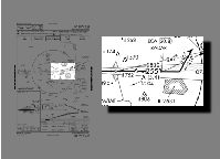
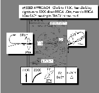
So, what if you can’t see the runway at decision height? As you might have expected, just as you can’t land willy-nilly, you can’t just go around willy-nilly. There’s a Procedure. A Missed Approach Procedure. This is shown in several places on the approach plate (see Figure 9.18): At the top, where it says “MISSED APPROACH”, in the plan view, where you can see a dashed arrow coming off the end of the runway and a dashed oval on the right, and in the profile view, where a series of boxes shows graphically what to do. In our case, these all tell us to:
- Climb straight ahead to 1100 feet
- Make a climbing right turn to 3000 feet
- Fly to REIGA
- Fly outbound from REIGA at 062∘
- Fly a holding pattern at the TRACY intersection
The holding pattern, as you might have guessed, is a place where you can “park” while sorting things out, and has its own set of procedures and techniques which we won’t go into here, because …
9.4.13 Touchdown
In our ideal simulator world, you probably won’t have to execute a missed approach. Assuming you stayed on the glide slope, you should have popped out of the murk at 750 feet, a whole 153 feet above the decision height, and with 1 mile visibility, the runway should have been in view soon afterSight runway; disengage autopilot; cross middle marker. With the runway in sight, you could then turn wildly to get on course20 (it’s very hard to be lined up perfectly) and land “normally” (which for me involves a lot of bouncing around and cursing)Land; eat hamburger. Park the plane, then stagger out of the cockpit and have another hamburger!
9.5 Epilogue
That was a lot of information in a short time, a rather brutal introduction to ILS flying. Hopefully, instead of turning you off, it has whetted your appetite for more, because there is more. Some of the major issues I’ve ignored are:
- Wind
- This is a big one. Flying IFR in a crosswind affects everything you do, and you need to be aware of it or your navigation will suffer.
- Flying without the autopilot
- George tries his best, but he’s not completely trustworthy. You have to be prepared to go it alone.
- DG precession
- The directional gyro in the c172p is not perfect. Over time, the values it gives you are less and less reliable — it precesses. It needs to be periodically calibrated against the compass (using the OBS knob on the DG to adjust it).
- IFR charts
- We used sectionals, which are really intended for VFR flight. There are a whole set of charts devoted exclusively to IFR flight.
- ATC
- The other people out there need to know what you’re doing. As well, they’ll probably tell you what to do, including to ignore the approach plate you so fastidiously studied.
- SIDs/DPs, Airways, and STARs
- This tutorial introduced IAPs, which are standard ways to make approaches. In IFR flight, there are standard ways to leave airports (Standard Instrument Departures, SIDs, or Departure Procedures, DPs), standard ways to travel between airports (airways), and standard ways to go from airways to IAPs (Standard Terminal Arrival Routes, STARs).
- Holding Patterns
- Most missed approaches end in a holding pattern somewhere, so you’d better know how to fly them.
- GPS
- Our Cessna doesn’t have a GPS, but nowadays most small planes do, and GPS is rapidly replacing radio-based navaids.
If you want to learn more, try the following resources:
-
Flight Simulator
Navigation, written by Charles Wood. It covers everything from basic navigation
to ILS approaches, with lots of examples and practice flights to improve your skills.
Everything is linked together by an entertaining storyline in which you are the pilot for a
fictional charter service.
Two caveats, though. First, it is Microsoft Flight Simulator-based, so you’ll have to translate into “FlightGear-ese” as appropriate. Second, it is a bit out of date, and things in the real world have changed since it was written. NDB beacons have been decommissioned, new approaches have replaced old ones — even an airport has disappeared (!). Treat this as a learning opportunity. You’ll get better at finding more up to date information, and learn not to blindly trust your charts, just as you have learned not to blindly trust your instruments.
- If you’re really keen and want to hear it straight from the horse’s mouth, there’s the official FAA Instrument Flying Handbook. It’s big and detailed, and there’s no interesting storyline in which you’re a pilot for a fictional charter service. It can be downloaded as multiple PDF files.
- If you’d like practice deciphering what the instruments are telling you, without the bother flying (or even virtual flying), you can try luizmonteiro.com, which has Flash tutorials of various instruments, including a VOR and an ADF.
- Another simulated instrument site is Tim’s Air Navigation Simulator. It has a Java applet that simulates a plane flying in the vicinity of two navaids. The simulation allows you to use different kinds of instruments and navaids, so you can see their behaviour, and the advantages and disadvantages of each.
- If it’s navigation information you’re after, an excellent site is AirNav.Com, which I’ve used extensively in the course of this tutorial. It has detailed airport, navaid, and fix information, and links to IAPs. Unfortunately, the information is only for the USA.
- Another source of airport and navaid information is World Aero Data. Its information isn’t as detailed as AirNav’s, but it is international.
-
FlightSim.Com has a very informative series of
articles entitled
“How To … Use
Approach Plates”. It starts with a very,
very dense tutorial on how to read an approach plate, then follows with a set of
approaches at Kodiak, Alaska. These are an excellent supplement to the approaches given in
Charles Wood’s Flight Simulator Navigation (see
above).
Most interesting, though, is section two — “Dangerous Approaches.” Approaches at six airports around the world, from Penticton, BC to Kathmandu, Nepal, are described. Fly them if you dare!
Warning — the series is even more Microsoft Flight Simulator-centric than Charles Wood’s, and some of it is out of date (some outside links are broken, and some of the approaches have changed).
- Also from FlightSim.Com is “Golden Argosy”, a description of a flight from New York to Rome by Tony Vallillo, an American Airlines 767 captain. It gives some interesting information about navigation that doesn’t appear in the other sites mentioned here, such as the North Atlantic Tracks. However, its main appeal is that it gives a good answer to the question “What’s it really like to be a pilot?” The author’s love of flying is evident throughout the article.
- For those who are interested in the ATC side of things, and want information from an authoritative source, check out Michael Oxner’s “Aviation Topic of the Week”, a series of articles about flying “in many types of airspaces in many situations.” Michael Oxner is a professional controller and private pilot who obviously can’t get enough of airplanes, because in his spare time he’s also an on-line controller with VatSim. Particularly interesting are a set of articles describing a complete IFR flight and a complete VFR flight.
- Freeworld Airways is a virtual airline. Their
“flight school”
has lots of useful information about navigation (including holding patterns, SIDs, and
STARs), ATC and communication, and weather.
Also interesting are two example flights, one in Europe and one in North America, showing the interaction between pilot and ATC.
Footnote Text
1 In fact, you might have to make it even uglier, if you use csh or tcsh. They’ll complain about the square brackets, so you’ll need to escape them: …visibility-m\[0\]…. If you really don’t like this, you can also set this option from the FlightGear menu: click Environment ⇒ Weather Conditions, and set the visibility in the 3000 foot layer to 30000. back
2 See http://en.wikipedia.org/wiki/VHF_omnidirectional_range for more information. back
3 Operation of the COMM receivers was covered in the cross country flight tutorial. back
4 All important actions and events will be given in the margin. This should provide a nice summary of the flight, uncluttered by the verbiage of the text. back
5 The horizontal needle is used in ILS landings, which will be explained later. back
6 If you get tired of clicking on the knobs, much of this can be done more easily using the Equipment ⇒ Radio Settings dialog. back
7 Of course, you don’t really have to do this — you could just watch the altimeter, and when it gets to 4000 feet, reduce the vertical speed to 0, or press the ALT button to enter altitude hold mode. But by using the altitude select knob, we’ve demystified one more mystery button. back
8 Unless you’re heading in the opposite direction, but that’s another story. back
9 See http://en.wikipedia.org/wiki/Distance_Measuring_Equipment for more information. back
10 For example, from http://www.airnav.com/airspace/fix/SUNOL . back
11 See http://en.wikipedia.org/wiki/Non-directional_beacon for more information. back
12 Antenna mode, by the way, is usually used to ident an NDB, because it gives better audio reception. While in antenna mode, however, the ADF will not point to the station — the needle will be parked pointing directly right. back
13 Which is actually bad technique in the presence of a crosswind, but I’m ignoring the wind to simplify the tutorial. back
14 The timer can also be set to count down from a time you specify — except that feature has not yet been implemented. back
15 Way off course, actually. I’ve exaggerated the angles to make the explanation clearer. back
16 You might be thinking “Wouldn’t it be nice if there was an ADF where the compass card rotated automatically?” Well, such an ADF does exist, and it comes with its own acronym — RMI (Radio Magnetic Indicator). back
17 See http://en.wikipedia.org/wiki/Instrument_Landing_System for more information. back
18 Well, unless it’s a Category IIIC ILS approach. back
19 As you may have guessed, the remaining light — white, and labelled “A” — indicates passage of the inner marker. Our approach doesn’t have one, but San Fransisco’s runway 28R does. While passing over it, you should hear a rapid, high-pitched series of dots. Why is it labelled “A” and not “I”? Because in ancient times, it was also used to identify passage over “airway” markers along radio range tracks. back
Google Advertisements - Click to support FlightGear